|
|
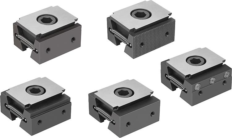
DescriptionProduct description:The functioning principle make the wedge clamps ideal for multi-clamping.
The wedge shape creates high clamping forces.
The wedge clamps can be used for clamping in conjunction with the clamping rail or mounted in tapped holes or T-slots.
Tightening the clamping screw moves the two clamping segments outwards and press the workpieces against the fixed jaws of the machining fixture.
The double wedge has an elongated hole allowing for movement and to compensate for tolerances.
Displacement: M12 = ±1 mm, M16 = ±1.5 mm.Material:Double wedge and clamping segments mild steel.Version:Double wedge and clamping segments hardened, phosphated.Note:The two screw-on holes in the clamping faces also enable seating ledges to be mounted so as to optimise the clamping depth of the workpieces.Supplied withWedge clamps.
Fastening screw.Drawing reference:Form A: Smooth jaw face
Form B: Serrated jaw facet
Form C: With step
Form D: With machining allowance
Form E: With jaw pins DownloadHere is all the information as a PDF datasheet:
Are you looking for CAD data? These can be found directly in the product table.
|
Drawings (total overview) |
| | | | | | | | | | | | | | | | | | Reset |
|---|
| Order No. | Form | Form definition | L
min. | L
max. | B
| H | B1 | H1 | H3 | D
Internal
thread | Z
cap screw
DIN 912 | Clamping
force
max. kN | Tightening
torque
max. Nm | CAD | Acc. | Price | Order |
|---|
| 41501-0500112 | A | smooth | 44,5 | 50,5 | 50 | 25 | 30 | 12,5 | 3,5 | M5 | M12x25 | 30 | 85 |  | | on request | | | 41501-0720112 | A | smooth | 61 | 68 | 72 | 39,7 | 44 | 21,3 | 3,5 | M6 | M12X40 | 30 | 85 | | | on request | | | 41501-0720116 | A | smooth | 61 | 68 | 72 | 39,7 | 44 | 21,3 | 3,5 | M6 | M16X40 | 50 | 150 | | | on request | | | 41501-1000116 | A | smooth | 71,5 | 81,5 | 100 | 42,6 | 64 | 21,6 | 5 | M8 | M16X40 | 50 | 150 | | | on request | |
|
| | | | | | | | | | | | | | | | | | Reset |
|---|
| Order No. | Form | Form definition | L
min. | L
max. | B
| H | B1 | H1 | H3 | D
Internal
thread | Z
cap screw
DIN 912 | Clamping
force
max. kN | Tightening
torque
max. Nm | CAD | Acc. | Price | Order |
|---|
| 41501-0500212 | B | serrated | 44,5 | 50,5 | 50 | 25 | 30 | 12,5 | 3,5 | M5 | M12x25 | 30 | 85 | | | on request | | | 41501-0720212 | B | serrated | 61 | 68 | 72 | 39,7 | 44 | 21,3 | 3,5 | M6 | M12X40 | 30 | 85 | | | on request | | | 41501-0720216 | B | serrated | 61 | 68 | 72 | 39,7 | 44 | 21,3 | 3,5 | M6 | M16X40 | 50 | 150 | | | on request | | | 41501-1000216 | B | serrated | 71,5 | 81,5 | 100 | 42,6 | 64 | 21,6 | 5 | M8 | M16X40 | 50 | 150 | | | on request | |
|
| | | | | | | | | | | | | | | | | | | Reset |
|---|
| Order No. | Form | Form definition | L
min. | L
max. | B
| H | B1 | H1 | H2 | H3 | D
Internal
thread | Z
cap screw
DIN 912 | Clamping
force
max. kN | Tightening
torque
max. Nm | CAD | Acc. | Price | Order |
|---|
| 41501-0502312 | C | 2 mm steps | 50,5 | 56,5 | 50 | 25 | 30 | 12,5 | 2 | 3,5 | M5 | M12x25 | 30 | 85 | | | on request | | | 41501-0505312 | C | 5 mm steps | 50,5 | 56,5 | 50 | 25 | 30 | 12,5 | 5 | 3,5 | M5 | M12x25 | 30 | 85 | | | on request | | | 41501-0722316 | C | 2 mm steps | 67 | 74 | 72 | 39,7 | 44 | 21,3 | 2 | 3,5 | M6 | M16X40 | 50 | 150 | | | on request | | | 41501-0725316 | C | 5 mm steps | 67 | 74 | 72 | 39,7 | 44 | 21,3 | 5 | 3,5 | M6 | M16X40 | 50 | 150 | | | on request | | | 41501-1002316 | C | 2 mm steps | 77,5 | 87,5 | 100 | 42,6 | 64 | 21,6 | 2 | 5 | M8 | M16X40 | 50 | 150 | | | on request | | | 41501-1005316 | C | 5 mm steps | 77,5 | 87,5 | 100 | 42,6 | 64 | 21,6 | 5 | 5 | M8 | M16X40 | 50 | 150 | | | on request | |
|
| | | | | | | | | | | | | | | | | | Reset |
|---|
| Order No. | Form | Form definition | L
min. | L
max. | B
| H | B1 | H1 | H3 | D
Internal
thread | Z
cap screw
DIN 912 | Clamping
force
max. kN | Tightening
torque
max. Nm | CAD | Acc. | Price | Order |
|---|
| 41501-0500412 | D | with machining allowance | 54,5 | 60,5 | 50 | 25 | 30 | 12,5 | 3,5 | M5 | M12x25 | 30 | 85 | | | on request | | | 41501-0720412 | D | with machining allowance | 71 | 78 | 72 | 39,7 | 44 | 21,3 | 3,5 | M6 | M12X40 | 30 | 85 | | | on request | | | 41501-0720416 | D | with machining allowance | 71 | 78 | 72 | 39,7 | 44 | 21,3 | 3,5 | M6 | M16X40 | 50 | 150 | | | on request | | | 41501-1000416 | D | with machining allowance | 81,5 | 91,5 | 100 | 42,6 | 64 | 21,6 | 5 | M8 | M16X40 | 50 | 150 | | | on request | |
|
| | | | | | | | | | | | | | | | | | | | | | Reset |
|---|
| Order No. | Form | Form definition | L
min. | L
max. | B
| H | B1 | B2 | H1 | H3 | H4 | H5 | H6 | D
Internal
thread | Z
cap screw
DIN 912 | Clamping
force
max. kN | Tightening
torque
max. Nm | CAD | Acc. | Price | Order |
|---|
| 41501-0500512 | E | with pins | 54 | 60 | 50 | 25 | 30 | 18 | 12,5 | 3,5 | 5 | 9 | 4,75 | M5 | M12x25 | 30 | 85 | | | on request | | | 41501-0720512 | E | with pins | 70,2 | 77,6 | 72 | 39,7 | 44 | 27 | 21,3 | 3,5 | - | 9 | 4,75 | M6 | M12X40 | 30 | 85 | | | on request | | | 41501-0720516 | E | with pins | 70,2 | 77,6 | 72 | 39,7 | 44 | 27 | 21,3 | 3,5 | - | 9 | 4,75 | M6 | M16X40 | 50 | 150 | | | on request | | | 41501-1000516 | E | with pins | 81,5 | 90,5 | 100 | 42,6 | 64 | 40 | 21,6 | 5 | - | 9 | 4,75 | M8 | M16X40 | 50 | 150 | | | on request | |
|
Other items in this category |
|
|

")

")
")
")
")
")
")


